Preventive Maintenance of Diesel Generator
1.0 Objective
To lay down a procedure Preventive Maintenance of Diesel Generator
2.0 Scope
This Standard Operating Procedure is applicable for Preventive Maintenance of Diesel Generator to be followed at formulation plants
3.0 Responsibility
3.1 Officer / Executive Engineering shall be responsible for the execution of this procedure.
3.2 Engineering Manager shall be responsible for the implementatio of this SOP.
3.3 Head QA/designee shall be responsible for compliance of this SOP.
4.0 Abbreviations and Definitions
SOP : Standard Operating Procedure
No : Number
QA : Quality assurance
Qty : Quantity
DG : Diesel Generator
5.0 Procedure
5.1 General Conditions
5.1.1 Refer the master plan of preventive maintenance.
5.1.2 Equipment shall be available for preventive maintenance.
5.1.3 Clean oil / grease stains & remove unwanted material, spares after completion of work.
5.2 Precautions
5.2.1 Use necessary safety wears, while doing the work.
5.2.2 Ensure covers & guards are properly fixed.
5.3 Procedure for Preventive Maintenance of Diesel Generator 1500 KVA.
5.3.1 Ensure that electrical supply is in off position in main panel and display “Under Maintenance” Board on the panel board.
5.3.2 Switch OFF the drive unit and inform all the concerned.
5.3.3 Operator or above has to ensure and verify the check points for the preventive maintenance as shown in the Annexure-1.
5.3.4 After the completion of preventive maintenance, check the machine for smooth operation.
5.3.5 Remove “Under Maintenance” Board on the panel board after completion of the maintenance.
5.3.6 The operator / technician who performs the job will enter his name / sign in “Done By” Column and responsible Engineer/ Officer will put sign in “Checked by “column Department head will review the record every month.
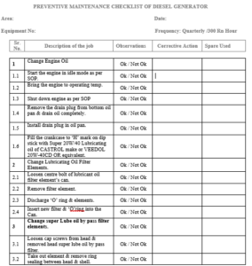
5.4 B’ Check Maintenance (After 300 running hours):
5.4.1 Change Engine Oil.
5.4.2 Start the engine in idle mode.
5.4.2.1 Bring the engine to operating temperature.
5.4.2.2 Shut down engine as per SOP.
5.4.2.3 Remove the drain plug from bottom oil pan and drain oil completely.
5.4.2.4 Install drain plug in oil pan.
5.4.2.5 Fill the crankcase to ‘H’ mark on dip stick with Dissolve Super 20W/40 Lubricating oil of CASTROL make or VEEDOL 20W-40CD or equivalent.
5.4.3 Change lubricating oil filter elements.
5.4.3.1 Loosen center bolt of lubricant oil filter element’s Can.
5.4.3.2 Remove filter element.
5.4.3.3 Discharge ‘O’ Ring and elements.
5.4.3.4 Insert new filter element & ‘O’ ring in to the Can.
5.4.3.5 Install can and element, assembly with its mounting bolt and washer.
5.4.3.6 Remove NPTF plug on can, fill some oil and replace the plug.
5.4.4 Change super Lube oil by pass filter elements.
5.4.4.1 Loosen cap screws from head and removed head super lube oil by pass Filter.
5.4.4.2 Take out element and remove ring sealing between head & shell.
5.4.4.3 Replace ring sealing and element.
5.4.4.4 Fill the filter with Lube oil and re-assemble it.
5.4.5 Check Engine coolant.
5.4.5.1 Take out 25ml coolant sample from engine in the beaker.
5.4.5.2 Dip one strip of pH paper in the coolant sample and compare the colors with the chart on the pH paper.
5.4.5.3 PH should be between 8.5 and 10, if less than 8.5 add the pH controller in the coolant to achieve mention value.
5.4.6 Change Corrosion Resistance Element.
5.4.6.1 Loosen the bolt from head and remove old elements.
5.4.6.2 Replace the new “Corrosion Resistance” elements and assemble the housing.
5.4.6.3 Top up the coolant water with De-mineralized water.
5.4.7 Change fuel filter element.
5.4.7.1 Loosen cap screw of fuel oil filter housing.
5.4.7.2 Remove filter element and ‘O’ ring and discard ‘O’ ring and elements.
5.4.7.3 Install new filter element and ‘O’ ring in to the filter housing.
5.4.7.4 Fill housing with fuel and assemble shell to head with cap screw.
5.4.8 Air Intake System
5.4.8.1 Check air intake pipe connection, tighten up.
5.4.8.2 Clean the Air filter elements if it is damaged or clogged replace it.
5.4.8.3 Clean crankcase breather.
5.4.9 Exhaust Air System.
5.4.9.1 Check the leakage and arrest them.
5.4.9.2 Check and clean exhaust restriction.
5.4.10 Engine
5.4.10.1 Check the engine for unusual vibration if found prevent them with correcting the alignment.
5.4.10.2 Tighten up foundation bolts.
5.4.10.3 Clean the engine with help of wet and dry mopping.
5.4.11 Alternator
5.4.11.1 Check and tight the electrical connection and winding connection.
5.4.11.2 Apply the Grease over bearing.
5.4.11.3 Clean the auto voltage regulator with the help of Air Blower
5.4.12 Electrical
5.4.12.1 Check the battery charging system.
5.4.12.2 Check the electrolyte level and specific gravity, if required top up.
5.4.12.3 Check the safety control and alarms circuit.
5.4.12.4 Check the Automatic start operation.
5.4.12.5 Check and tight the all-electrical connection.
5.4.12.6 Check and clean the Air Circuit Breaker contact with help of CRC.
5.4.12.7 Lubricate the Air Circuit Breaker linkage.
5.5 For “C” check after 1500 running hours and “ D” check after 2500 running hours, call the external agency.
6.0 Forms and Records
6.1 ‘B’ Check Preventive Maintenance Check list of Diesel Generator – Annexure-1
7.0 Distribution
7.1 Master copy – Documentation Cell (Quality Assurance)
7.2 Controlled copies – Engineering Department