performance qualification protocol for water for injection
| EQUIPMENT ID. No. | |
| LOCATION | WFI GENERATION AREA |
| SUPERSEDES PROTOCOL No. | NIL |
PROTOCOL CONTENTS
| S. NO. | TITLE | PAGE NO.
|
| 1.0 | PROTOCOL APPROVAL | |
| 2.0 | OBJECTIVE | |
| 3.0 | SCOPE | |
| 4.0 | RESPONSIBILITY | |
| 5.0 | EQUIPMENT DETAILS | |
| 6.0 | SYSTEM DESCRIPTION | |
| 7.0 | REASON FOR QUALIFICATION | |
| 8.0 | SITE OF STUDY | |
| 9.0 | FREQUENCY OF QUALIFICATION | |
| 10.0 | PRE-QUALIFICATION REQUIREMENTS | |
| 11.0 | TESTS AND CHECKS (PROCEDURE) | |
| 12.0 | CHECKLIST OF ALL TESTS & CHECKS | |
| 13.0 | REFERENCES | |
| 14.0 | DOCUMENTS TO BE ATTACHED | |
| 15.0 | NON COMPLIANCE, IF ANY | |
| 16.0 | DEVIATION FROM PRE–DEFINED SPECIFICATION, IF ANY | |
| 17.0 | CHANGE CONTROL, IF ANY | |
| 18.0 | ABBREVIATIONS | |
| 19.0 | REVISION HISTORY |
1. PROTOCOL APPROVAL:
PREPARED BY:
| DEPARTMENT | NAME | DESIGNATION | SIGNATURE/DATE |
| QUALITY ASSURANCE |
REVIEWED BY:
| DEPARTMENT | NAME | DESIGNATION | SIGNATURE/DATE |
| QUALITY ASSURANCE | |||
| ENGINEERING | |||
| PRODUCTION | |||
| QUALITY CONTROL |
APPROVED BY:
| DEPARTMENT | NAME | DESIGNATION | SIGNATURE/DATE |
| HEAD QUALITY ASSURANCE |
2. OBJECTIVE:
• To establish the methodology for the performance qualification of WFI system, which is used for generation, storage and distribution of WFI .
• To ensure that WFI meets the Pharmacopoeial specifications of IP, BP and USP.
• To confirm the appropriateness of critical parameters of the WFI system components.
• To establish reliability of WFI system. To establish Alert and Action levels.
• To establish the efficacy of sanitization procedures.
• To validate the system and check its performance for one year in order to cover all the seasonal variations.
• The WFI system performs as per the pre-defined parameters and/or quality attributes.
3. SCOPE:
• The Protocol covers all aspects of Performance Qualification for the WFI Generation System installed in the WFI Generation Area at …….
• This Protocol will define the methods and documentation used to qualify the WFI system for Performance Qualification.
4. RESPONSIBILITY:
• The Validation Group, comprising of a representative from each of the following departments, shall be responsible for the overall compliance of this Protocol.
| DEPARTMENTS | RESPONSIBILITIES |
| Quality Assurance | · Preparation, Review of the Performance Qualification Protocol.
· Protocol Training. · Co-ordination with Production and Engineering to carryout Performance Qualification Activity. · Monitoring of Performance Qualification Activity. |
| Production | · Review & Approval of Protocol.
· To co-ordinate and support Performance Qualification Activity. |
| Quality Control | · Review & Approval of Protocol.
· To co-ordinate and support Performance Qualification Activity. |
| Engineering | · Review & Approval of Protocol.
· Co-ordination, Execution and technical support in Performance Qualification activity. · Calibration of Process Instruments. · Responsible for Trouble shooting (if occurs during execution). |
5. EQUIPMENT DETAILS:
| Equipment Name | WFI System |
| Equipment ID. | |
| Manufacturer’s Name | Afftech Pharma Machine |
| Capacity | 500 Litre/Hour |
| Location of Installation | WFI Generation Area |
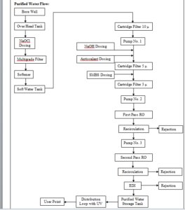
6. SYSTEM DESCRIPTION:
A. WFI System:
The WFI system design has the following major stages of purification, distribution and control.
After Purified water then one multi column for preparation of WFI and WFI storage tank and distribution system.
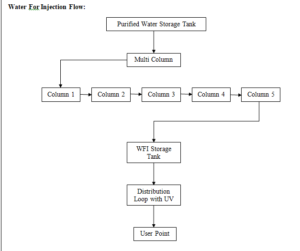
B. Generation System for WFI:
From Purified water storage tank to fed the purified water in to the multicolumn. Distillation unit from the multi column the WFI produced is stored in a SS Tank which has a holding capacity 500 Litre.
The WFI kept under circulation through loop and its temperature.
The WFI is kept under circulation through a loop and it’s temperature is always maintained above 80 o C. Temperature and Conductivity sensors are fitted on the return loop line. This is a full proof system developed by Fast Pharma for the production requirement of Parenterals Preparation.
C. Storage and Distribution System Description:
The WFI, generated by water system, is fed to the “WFI storage tanks, on demand, prior to the distribution to final user points. The storage tanks capacities have been arrived at, keeping in mind the peak load & buffer volumes to be maintained.
The WFI, stored in the “WFI storage tanks, is supplied to various usage points in the plant, by means of a piping/distribution network, which is a “closed loop system”. The water piping/distribution system is being maintained at ambient temperature.
D. WFI Storage Tanks:
Water storage tanks have been provided, for Injection Block. The “WFI storage tanks have been designed as jacketed tanks, for heating with steam during sanitization. The sanitization is performed by activating a steam control valve, for maintaining the water distribution systems at an elevated temperature for a stipulated period of time.
For safe working of the water system, “water level controllers” have been provided in the storage tanks, which prevent the tanks from overflowing as well as safeguard the pumps from running dry. In case of high water level in storage tank, water can be diverted to the process water tank.
E. Conductivity Meter:
The quality parameters of WFI, such as conductivity, are continuously monitored and provide necessary control for the water system operation. In case of any deviation in the water quality, “necessary tripping/alarm” is triggered, in order to draw the attention of the system operator. For this purpose, an “online conductivity sensor” has been installed, which can actuate a drain / dump valve (on deviation from set limits) and prevent WFI from being distributed to the user points. This safeguards the users from using poor quality water.
F. WFI Distribution Loops:
WFI separate loops have been provided, parental department both the loops are identical in design and basic control systems, but are designed for the agreed user requirements for respective loops.
7. REASON FOR QUALIFICATION:
• New Equipment Installed at WFI Generation Area First Floor.
8. SITE OF STUDY:
• WFI Generation Area First Floor at …………….
9. FREQUENCY OF QUALIFICATION:
Re-qualification of the WFI System shall be carried out through the change control procedure in case of followings;
• After any major breakdown or after major modification.
• Change in location
10. PRE – QUALIFICATION REQUIREMENTS:
The below mentioned activities should be completed prior to commencing the Performance Qualification activity:
10.1 Verification of Documents:
The below mentioned activities should be completed prior to commencing the performance Qualification activity:
• Verifying the SOP for Operation & Cleaning of WFI Generation System.
• Verifying the SOP for Preventive Maintenance of WFI Generation System.
10.2 Training Record of Validation Team:
• All the persons involved in the execution of Qualification activity must be trained in all aspects of the Qualification activity including the test methodology, acceptance criteria and safety precautions to be followed during working.
• Verify the training records and record the details in table mentioned in performance Qualification report.
10.3 Calibration of Test Instruments:
• Calibration of all the instruments used for Qualification should be mentioned along with Calibration Certificates.
The Performance Qualification of WFI system shall be carried out as following.
Phase-1, Phase-2 & Phase-3
- Phase-1 – Extensive sampling from Generation points & all usage points for 21 days .
Start Date: Completion Date
- Phase-2 – Extensive sampling from generation & all usage points for 21 days .
Start Date: Completion Date
- Phase-3 – Routine sampling from generation & all usage points on rotation basis as per schedule, for 12 months.
Start Date: Completion Date
The detailed methodology of the 3 phases of validation is as given below:
- Phase – 1: (For a period of 21 days)
Phase-1 of the performance qualification of water system shall include extensive sampling of water, from various points in the pre-treatment system and WFI generation system along with all the usage points of the distribution loops. The phase-1 sampling shall be carried out for a period of 21 days.
During this phase water samples from the generation / usage points shall be analyzed and monitored for compliance to the pre-determined specifications.
After successful completion of Phase-1 of the performance qualification, the WFI system shall be cleared for usage of WFI in manufacturing operations. Purpose of Phase-1 qualification is to stabilize the operating parameters and develop the cleaning / sanitization procedures / sanitization frequencies / sampling methods / drain time study and hold time study. Conclusions shall be described in a summary report.
- Phase – 2: (For a period of 21 days)
Phase-2 of the performance qualification shall commence, after successful completion of Phase-1. Purpose of Phase-2 qualification is to monitor the operating parameters as well as cleaning / Sanitization procedures / sanitization frequencies / sampling methods. The objective of Phase-2 is also to demonstrate that system will produce desired quality of water, on a consistent basis, when operated in conformance with SOP established at the end of Phase-1. Conclusions shall be mentioned in Summary report.
During Phase-2, water samples shall be collected from all the Sampling Points and Usage Points on a Daily basis (as per sampling plan). Phase-2 of the performance qualification of water system shall include extensive sampling of water, from all points in the WFI generation system & all the usage points of the distribution loops, daily. Phase-2 sampling shall be carried out for a period of 21 days.
Water samples from all usages points shall be analyzed and monitored, daily, for compliance to the pre-determined specifications.
After successful completion of Phase-2 of the performance qualification, the WFI system shall be cleared for Phase-3.
- Phase – 3: (For a period up to 12 months)
Phase-3 shall commence immediately after completion of Phase-2. The objective of Phase-3 is to demonstrate that the water system is capable of producing consistent quality water, by taking care of all possible seasonal variations, when operated in accordance with the established SOP’s over a long period of time. The sampling shall be done as per the routine sampling procedures. Samples shall be collected as per schedule (as per sampling plan). When the phase 3 is completed data shall be collected.
After Phase-3 routine monitoring schedule shall be frozen.
- Definition:
- Generation points: Generation system of WFI prior to Distribution loop systems termed as sampling points.
- Usage points: All the sampling points on distribution loop systems for termed as Usage point.
- Acceptance Criteria:
WFI from Different User Points
| Sr. No. | Test | Acceptance Limit |
| 1. | Description | Clear, colourless, odourless and tasteless liquid |
| 2. | pH | 5.0 to 7.0 |
| 3. | Conductivity | NMT 1.3 mS / cm (at 25 OC) |
| 4. | Nitrates | NMT 0.2 ppm (mg / Litre) |
| 5. | Heavy Metals | NMT 0.1 ppm (mg / Litre) |
| 6. | Acidity or Alkalinity | Should Comply |
| 7. | Oxidisable Substances | Should Comply |
| 8. | Total Organic Carbon | NMT 500 ppb |
| 9. | Bacterial Endotoxin Test | NMT 0.25 EU/ml |
| 10. | Total Aerobic Viable Count | NMT 10 cfu / 100 ml |
| 11. | Pathogens
1. Escherichia coli 2. Salmonella spp. 3. Staphylococcus aureus 4. Pseudomonas aeruginosa |
Absent |
- Performance Test:
Phase – I, II and III study will show the Feed Water and WFI quality throughout the year encompassing all seasonal variations in a year.
- Sampling and Testing Procedure
Follow respective standard operating procedures for sampling and testing.
- Sampling Points :
Following Sampling Points will be sampled and analyzed as per sampling schedule
| Sr. No. | Location | Sampling Point No. |
| 1. | Multicolumn Generation Point | SP 1 |
| 2. | Multicolumn 2 | SP 2 |
| 3. | Multicolumn 3 | SP 3 |
| 4. | Multicolumn 4 | SP 4 |
| 5. | Multicolumn 5 | SP 5 |
| 6. | WFI Storage tank – Reverse Loop | SP 6 |
| 7. | Ampoule 1 Washing Machine | SP 7 |
| 8. | Ampoule 2 Washing Machine | SP 8 |
| 9. | Liquid Vial Washing Machine | SP 9 |
| 10. | Liquid Injection Unit Preparation Area | SP 10 |
| 11. | Liquid Injection Manufacturing Room 1 | SP 11 |
| 12. | Liquid Injection Manufacturing Room 2 | SP 12 |
11.9 Sampling Schedule
11.9.1 Phase – I Study and Phase – II Study:
Carry out the Chemical and Microbiological analysis as per given schedule
| Sr. No. | Sampling Point No. | Schedule |
| 1. | SP 1 | Daily |
| 2. | SP 2 | Daily |
| 3. | SP 3 | Daily |
| 4. | SP 4 | Daily |
| 5. | SP 5 | Daily |
| 6. | SP 6 | Daily |
| 7. | SP 7 | Daily |
| 8. | SP 8 | Daily |
| 9. | SP 9 | Daily |
| 10. | SP 10 | Daily |
| 11. | SP 11 | Daily |
| 12. | SP 12 | Daily |
11.9.2 Phase – III Study:
Respective Sampling Points will be sampled and analyzed as per pre-determined specification on respective day
| Sr. No. | Sampling Point No. | Schedule |
| 1. | SP 1 | Daily |
| 2. | SP 2 | Once in Week |
| 3. | SP 3 | Once in Week |
| 4. | SP 4 | Once in Week |
| 5. | SP 5 | Once in Week |
| 6. | SP 6 | Daily |
| 7. | SP 7 | Once in Week |
| 8. | SP 8 | Once in Week |
| 9. | SP 9 | Once in Week |
| 10. | SP 10 | Daily |
| 11. | SP 11 | Daily |
| 12. | SP 12 | Daily |
11.9.3 Sampling Schedule : For Phase-III
| Monday | Tuesday | Wednesday | Thursday | Friday | Saturday |
| SP 1 | SP 1 | SP 1 | SP 1 | SP 1 | SP 1 |
| SP 2 | SP 3 | SP 4 | SP 5 | SP 6 | SP 6 |
| SP 6 | SP 6 | SP 6 | SP 6 | SP 10 | SP 10 |
| SP 7 | SP 8 | SP 9 | SP 10 | SP 11 | SP 11 |
| SP 10 | SP 10 | SP 10 | SP 11 | SP 12 | SP 12 |
| SP 11 | SP 11 | SP 11 | SP 12 | NA | NA |
| SP 12 | SP 12 | SP 12 | NA | NA | NA |
11.10 Required SOP’s:
The water system operation will be carried out as per given SOPs:
a) Operation of Water System.
b) Cleaning of Cartridge filters.
c) Sanitization Procedure on Distribution loop system.
The program involves intensive daily sampling and testing of major process points at “Normal Operating Conditions.”
In the process, regeneration, sanitization procedure and storage period of water in the storage tank shall be established.
- Evaluation of Results
Phase – 1 Result
After completion of Phase-I, Alert and Action limits of testing parameters for WFI will be calculated as per given equation and these alert and action limits will be followed for further qualification of water system.
After completion of Phase-I, water can be used for Production Purpose.
Alert levels are levels or range that, when exceeded; indicate that a process may have drifted from its normal operating condition.
Alert levels constitute a warning and do not necessarily require a corrective action.
“Alert Level = Average + 2 X Standard Deviation”
Action levels are levels or range that, when exceeded, indicate that a process has drifted from its normal operating range. Exceeding an Action level indicates that corrective action should be taken to bring the process back into its normal operating range).
“Action Level=Average + 3 X Standard Deviation”
Note: Based on the Study of Drain time, conclusion will be drawn for the period of drainage of WFI before usage during process. Based on Hold Time study, conclusion will be drawn for WFI storage period in case it is required.
Phase – 2 Results
After successful completion of Phase – 2, frequency of regeneration, sanitization operation shall be finalized. The frequency obtained during Phase – 2 studies shall be followed in Phase – 3.
Phase – 3 Results
After successful completion of Phase – 3, data obtained during the process shall be compiled and conclusion shall be drawn considering the Seasonal variation factor.
The following procedure shall be used for performance qualification of
WFI generation, storage and distribution system:
- Ensure that water system has qualified for operational qualification.
- Sanitization shall be performed as per respective SOP.
- The phase-1 studies shall be done as per acceptance criteria. The observations of the study shall be recorded as per the format provided.
The data sheets shall be attached date wise. After completion of phase-I studies the graphical representation of the data of all the parameters shall be done individually and attached.
- The phase-2 studies shall be done as per acceptance criteria. The observations of the study shall be recorded as per the format provided. The data sheets shall be attached date wise. After completion of phase-2 studies the graphical representation of the data of all the parameters shall be done individually and attached.
- The phase-3 studies shall be done as per acceptance criteria. The observations of the study shall be recorded as per the format provided. The data sheets shall be attached date wise. After completion of phase-3 studies the graphical representation of the data of all the parameters shall be done individually and attached.
- CHECKLIST OF ALL TESTS & CHECKS:
This checklist is provided to ensure that all tests or checks required for this protocol have been executed.
| S. No. | Name of Test or Check | Execution
(Yes/No.) |
Verified By | Remark |
| 1. | Description | |||
| 2. | pH | |||
| 3. | Conductivity | |||
| 4. | Nitrates | |||
| 5. | Heavy Metals | |||
| 6. | Acidity or Alkalinity | |||
| 7. | Oxidisable Substances | |||
| 8. | Total Organic Carbon | |||
| 9. | Bacterial Endotoxin Test | |||
| 10. | Total Aerobic Viable Count | |||
| 11. | Pathogens
1. Escherichia coli 2. Salmonella spp. 3. Staphylococcus aureus 4. Pseudomonas aeruginosa |
13. REFERENCES:
The Principle References are as following:
• Validation Master Plan.
• IP, BP, and USP.
14. DOCUMENTS TO BE ATTACHED:
• Calibration certificates of test instruments.
• Any other relevant document.
15. NON COMPLIANCE, IF ANY:
All the Non-compliances of procedure, specifications, and sampling, analysis and documentation activities shall be monitored & recorded.
16. DEVIATION FROM PRE-DEFINED SPECIFICATION, IF ANY:
• In case of any deviation observed during PQ, inform to Head QA for necessary action.
• Document the deviation detail in observed deviation section.
• The Head QA will study the impact of deviation. If deviation is acceptable and it does not have an impact on operation as well as on performance of the machine & prepare final conclusion.
17. CHANGE CONTROL, IF ANY:
• If any change control is required during PQ, inform to Head QA for necessary action.
• Document the details observed.
• The Head QA will study the impact of change. If change is acceptable and it does not have an impact on operation as well as on performance of the machine & prepare final conclusion.
- ABBREVIATIONS:
| EN | : | Engineering |
| P | : | Protocol |
| WFI | : | Water for Injection |
| SOP | : | Standard Operating Procedure |
| mm | : | Millimeter |
| PPM | : | Parts per million |
| PLC | : | Programmable Logic Control |
| % | : | Percentage |
| QA | : | Quality Assurance |
| QC | : | Quality Control |
| w/v | : | Weight/Volume |
| °C | : | Degree Centigrade |
| EU/ml | : | Endotoxine Unit/ml |
| NLT | : | Not Less Than |
| cfu | : | Colony forming unit |
| SP | : | Sampling Point |
| Min. | : | Minute |
| Sec. | : | Second |
| m3 | : | Cubic Meter |
| WHO | : | World Health Organization |
19. REVISION HISTORY:
| Revision No. | Change Control No. | Detail of Changes | Reason for Change | Effective Date | Updated By |
| 00 | NA | NA | New Protocol |
performance qualification protocol for water for injection
Online Rejection in parenteral
Receipt of Batch from Production to Packing Department
sop for for Spillage Handling in parenteral area
sop for calibration of vessels with dipstick
sop for Cleaning of Bins and Containers
cip of mixing vessel and holding vessel
sop for Cleaning of Ampoule Filling and Sealing Machine
sop for Fogging in Sterile and Non Sterile Area
sop for for Filtration of Bulk Solution
sop for fumigation in production area
sop for post cleaning after media fill
sop for cip of mixing vessel mixing mobile vessel and holding vessel
sop for De-Bagging of Three Piece Vial Dropper Caps
sop for calibration and verification of check weigher
sop for Batch number and Manufacturing and Expiry Date Coding System
standard operating procedure machine history file
sop for operation and cleaning of Hand coder
sop for Cleaning and Handling and Silicone Tubes
sop on operation and cleaning of coating pan
sop for Operation of cleaning of pipe lines
sop for operation of capsule loading machine semi automatic
sop for Machine operation capsule inspection and polishing machine
Sop batch demarcation and batch coding
sop for monitoring of reprocessing of products
sop for in-process control on liquids orals
sop for in process controls on tablets capsules packaging line
sop for Issuance retrieval and destruction of BMR and analytical records
sop for in process controls during granulation compression coating inspection
sop for Cleaning of Blister packing machine
sop for for charge hand over between the shifts
Performance requalification report of visual inspectors
sop for Cleaning and operation of ROPP caps inspection table
sop for usage and destruction of filter pad and cartridge filter
sop for cleaning and storage of transfer pipe
sop for Cleaning and operation of labeling machine
Cleaning and operation of the mono block filling and sealing machine
sop for Cleaning and operation of empty bottle inspection table
sop for Cleaning and operation of filter press
sop for cleaning and operation of liquid transfer pump and line
sop for cleaning and operation of storage vessels
sop for cleaning and operation of sugar syrup manufacturing vessel
sop for cleaning issuance and retrieval of accessories and change parts
sop for Cleaning and operation of visual inspection conveyor belt
sop for Cleaning and operation of spray gun and assemble
sop for Fogging in Aseptic and Non Aseptic Area